
Prologue: how I got into Skating
One of my best friends from high school was a skater. He wasn't amazing at tricks or anything, but he would take his board to and from school, and he knew how to use it well. In other words, he was a functional skater. He eventually had to move away to Washington State due to changing family circumstances, but I've stayed in touch with him since.
I grew up riding a scooter, which anyone who is older than 16 will agree is actually pretty lame. I would sometimes go to a skate park near my house and practice tricks, but I never really progressed past basic jumps until I started going to the park with my friend. The peer pressure gave me the drive to start learning new skills at an unprecedented rate. I started learning to pump on curves and eventually to drop in and pop out of bowls.
Anyway, when my friend left, he gave me some skateboard trucks and wheels. He only had one carry-on bag to take with him, so he had to leave a lot. In the weeks following, I would steal my sister's unused cheapo Walmart board and fit it with the wheels and trucks I had received. The bearings were still abysmal, but that was acceptable for me, having never known a board could be much better.
I practiced it a bit but never progressed past simply using the board as a means of transportation. I also used my bike much more often, as it was much quicker and more efficient as a mode of transportation between classes at the community college, which was my primary use case. Once I got my license. I practically stopped using all other modes of transportation entirely. I would occasionally take the board and scooter to the skate park, but those trips were few and far between.
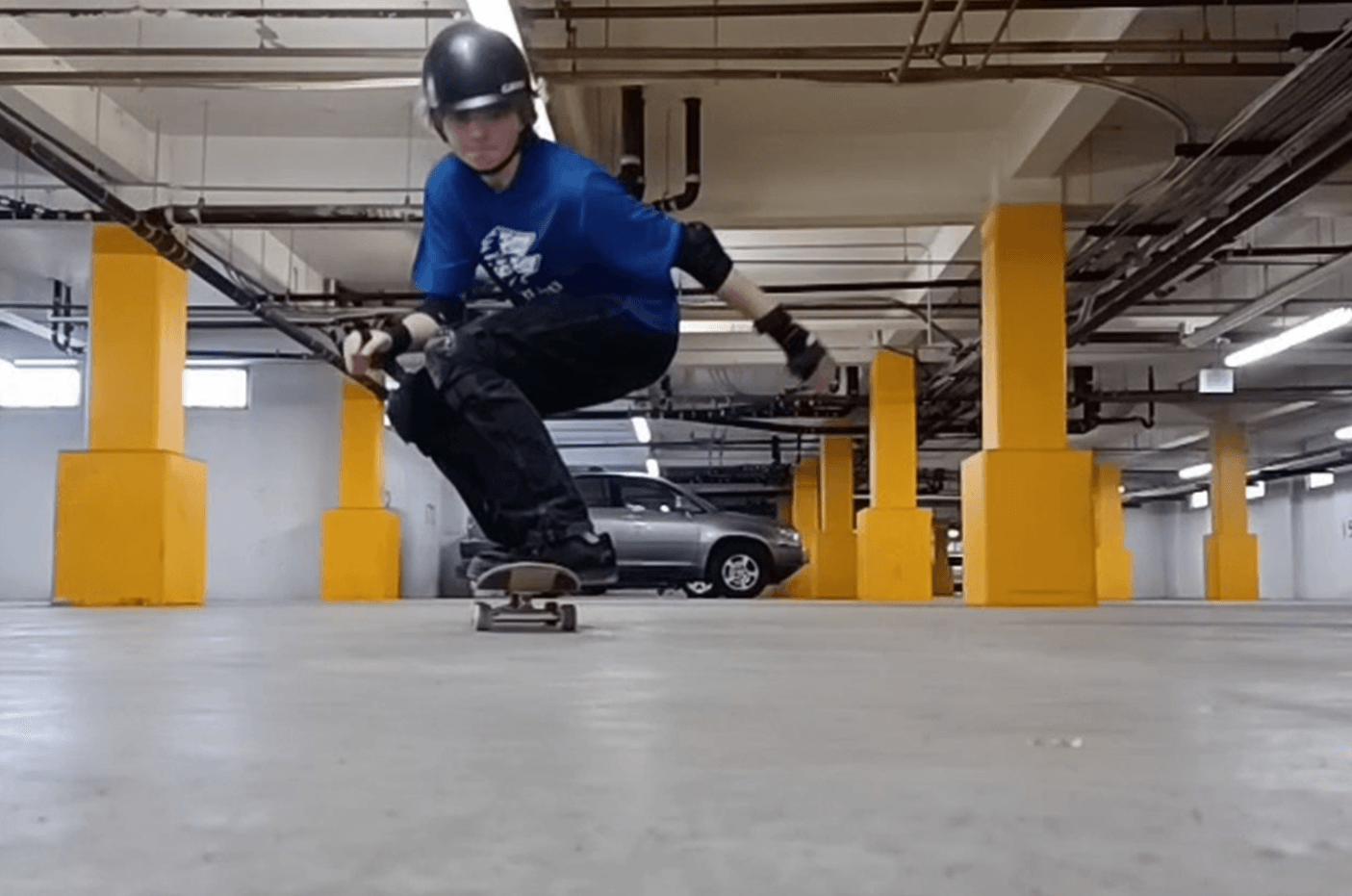
Even so, my friend in Washington was going all-in on skating. He found himself in need of reliable transportation to get a job, but at the same time strapped for cash (hence, why he needed a job). So, as any sane person would do, he chose to make an electric longboard. I don't know his exact build, but I knew that it was functional for him until he had enough to buy a car and that he looked really cool when he was riding it.
The Moment of Inspiration
When I arrived at the Colorado School of Mines campus for the fall 2026 semester, I knew that I wanted to get involved in a project, but I wasn't sure what. I had met a guy named Austin on the M-climb who seemed like a technically competent guy, and while talking with him, we somehow decided to work together on an electric longboard. I wish I had written this sooner, so the details would be clearer, but I'm just working with what I've got, so please don't shoot the messenger. That evening (or about), I started on the first CAD mockup of the design.
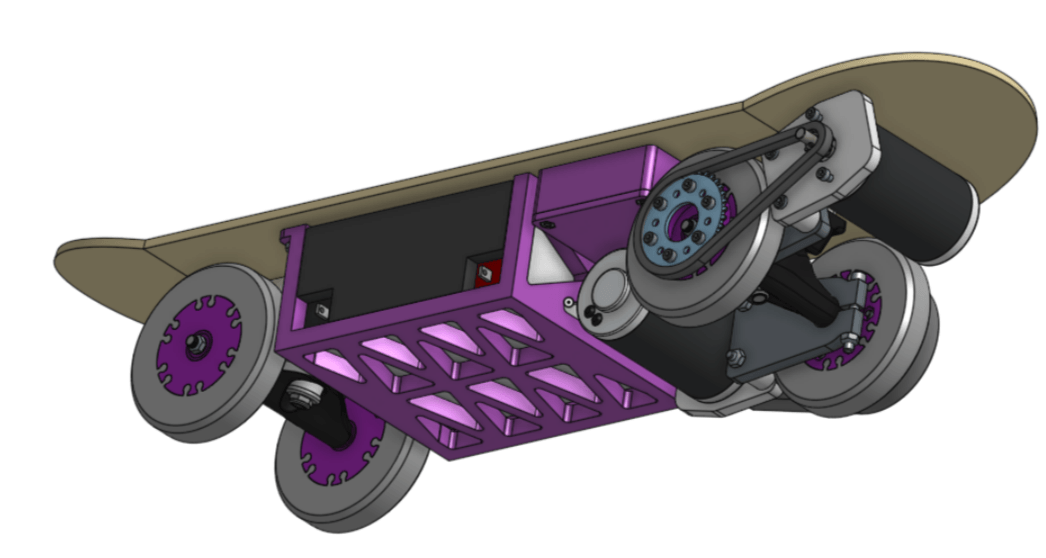
It's pretty evident from this that I am an FRC alum. I went with an FRC sealed lead acid battery, which is objectively the wrong choice for this type of project. I also chose to lift the board a bunch (2.5”). Lifting a board has a few different effects, not all of which are bad, but they make it somewhat weird to ride and make it worthwhile to avoid.
- Increases the effect of turning the board, usually resulting in a tighter turn radius
- Increases the speed of wear on the bushings, requiring them to be replaced sooner
- Decreases chance of wheel bite, when the board touches the wheels.
- Makes manually pushing the board much more awkward, since you have to crouch down more.
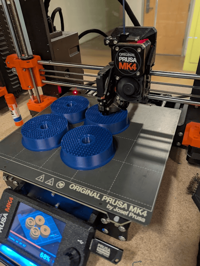
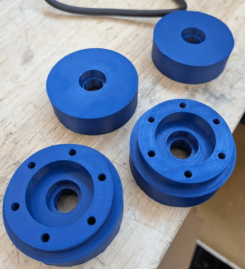
In order to accommodate the 3D-printed wheels, I needed to lift the board, so I made some massive PLA spacers to do that. I also 3D printed some wheel hubs, this time with higher density gyroid infill, and printed in PETG. Unfortunately, I didn't up the wall-loop count, which I eventually learned strengthens the part much more than simply upping the infill does.
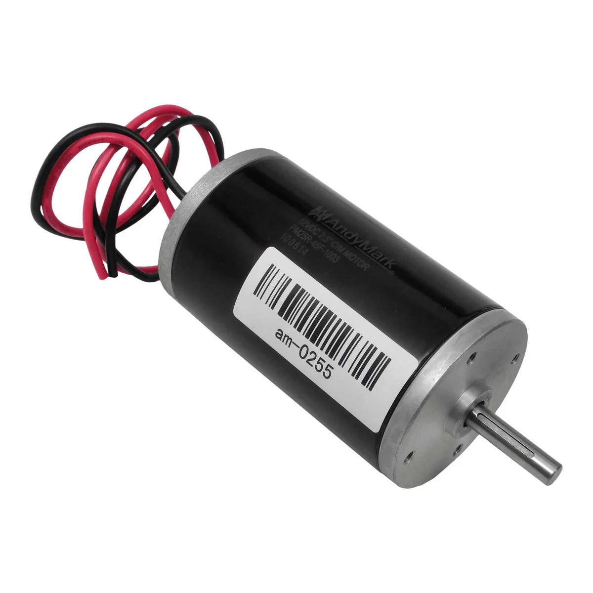
Additionally, this design used CIM motors, a staple of FRC until they were superseded by brushless options. I had these on hand, and I knew from experience that two of them would have more than ample top speed and torque to move a human.
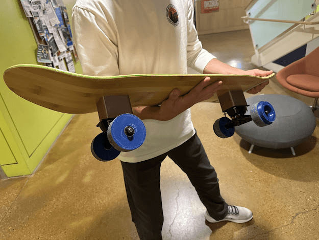
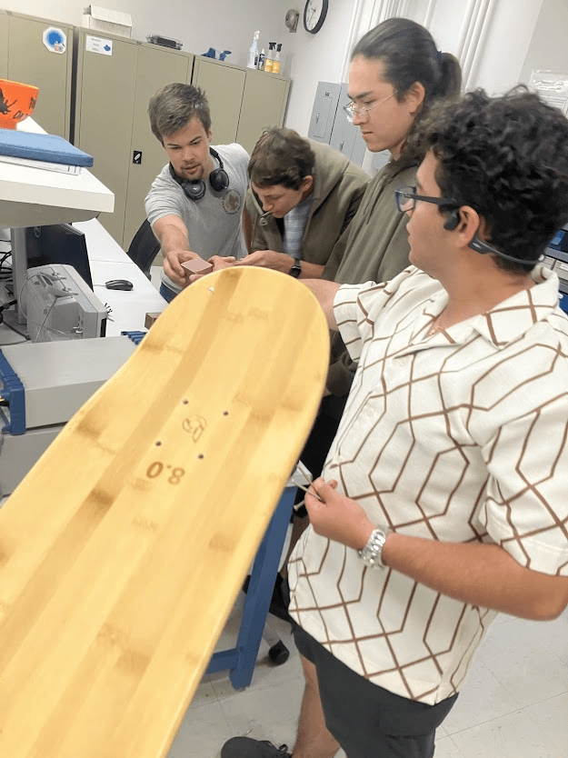
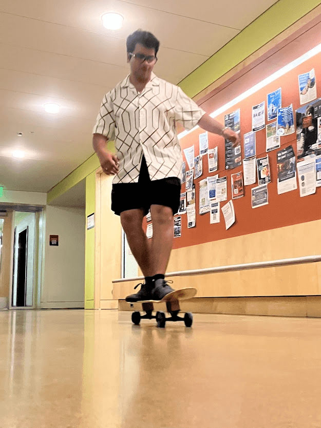
Regardless, that night, I slapped these onto a board that Austin had bought for the project, added some bearings, and took it for a spin. A bunch of my friends from the dorm came with, and we had a blast on the board, riding it around a bunch and learning the consequences of not knowing how to stop.
As you might have noticed from the picture above, the wheels should have had a TPU ring around them. I hadn't quite gotten to that point and instead was riding on bare PETG. When the wheels hit a slight bump, there was not enough load distribution, and one of the wheels cracked, launching me off. In retrospect it was pretty stupid, but you live and learn, I guess. The injuries weren't too bad. I scraped up my hands and knees, but they had fully healed within a week.
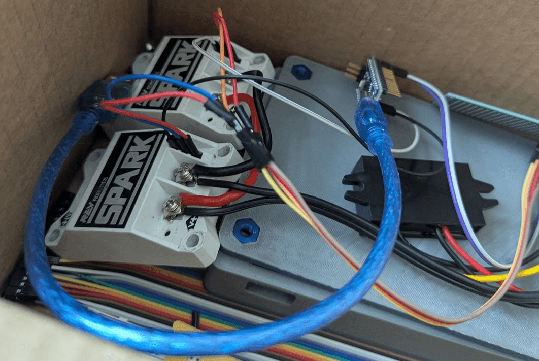
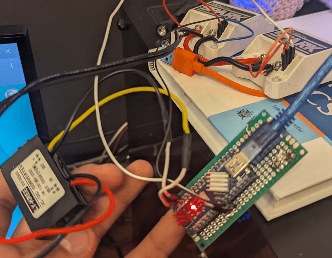
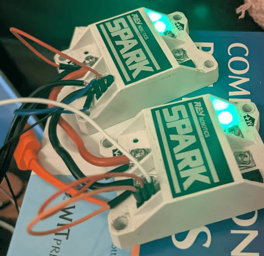
Over the next couple of weeks, I began working on the control system. I used an Arduino Nano and two REV Spark ESCs, primarily because those were the components I had on hand. Making hardware decisions is pretty easy when you only have one option to choose from. I also 3D-printed the housing out of PETG using captive nuts. Captive nuts are simply an amazing manufacturing method, and if you haven't learned how to use them, then you're missing out. While people rave about heat-set inserts, they're completely missing the OG method of adding metal threads to an FDM part.
Anyway, you'll see in this picture another little black electrical component. That guy is a DC-DC buck converter. It takes the input voltage from the batteries and regulates it down to a stable 5-volt supply for the electronics. This was important because the ESCs that I was using were capable of supplying a lot of volts of back-EMF, and it would allow me to pick batteries that slightly exceed 12 volts. (though not by much because 12 volts is the max for CIM motors)
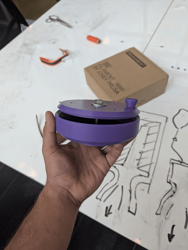
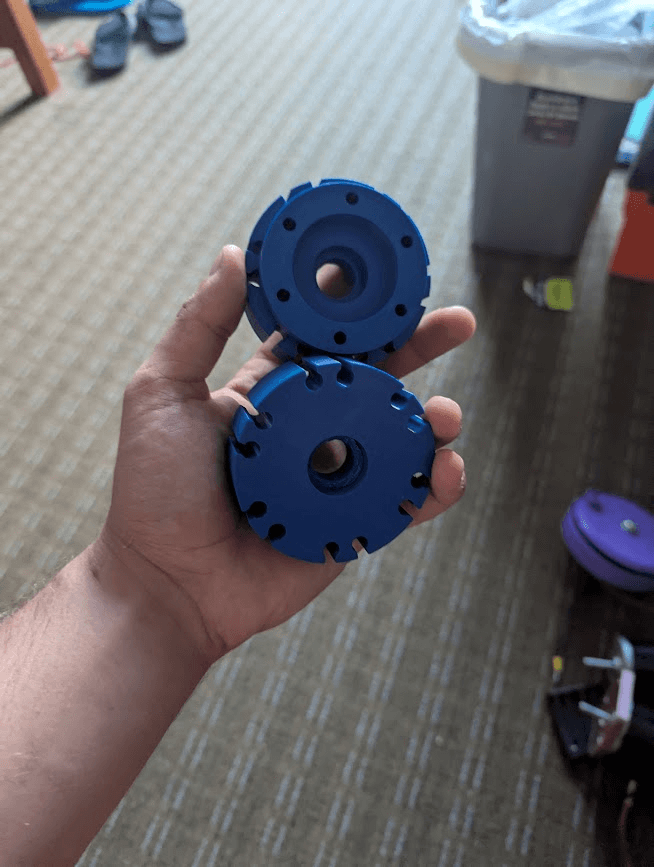
With these done, I also made the pivot to urethane-cast wheels for the skateboard. I did some internet searching and found that most skateboard wheels are cast in urethane. Solid 95A TPU would have likely held up similarly, but going the industry standard route didn't require all that much more money, and it would allow me to learn a new skill along the way. In the wheels, my initial design used small teardrop-shaped cutouts to allow the urethane to get interlocked into the hub, and then hope that the shear force would not tear it away. This design likely would have worked, and it allowed me to switch back to FDM TPU if the urethane didn't work, but I did eventually switch away from this design for the hubs.
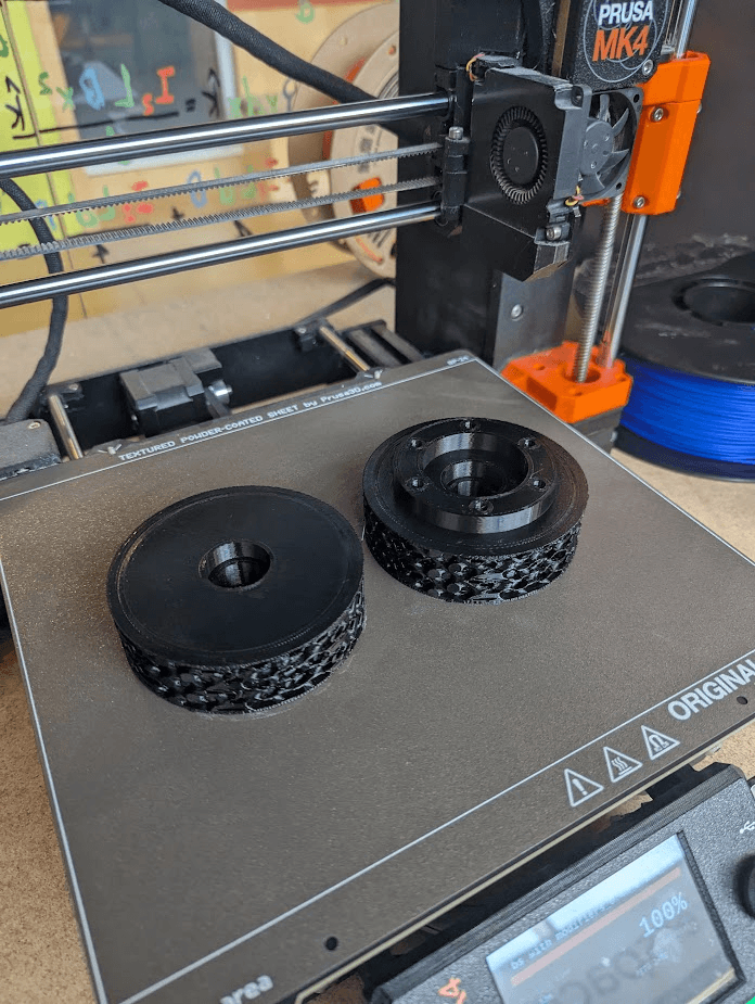
The new design that I went for utilized modifier meshes in my slicer software to make the outside a low-density gyroid pattern that the urethane could easily penetrate, and have more surface area to adhere to. These hubs performed exceedingly well, and I've never had to modify them.
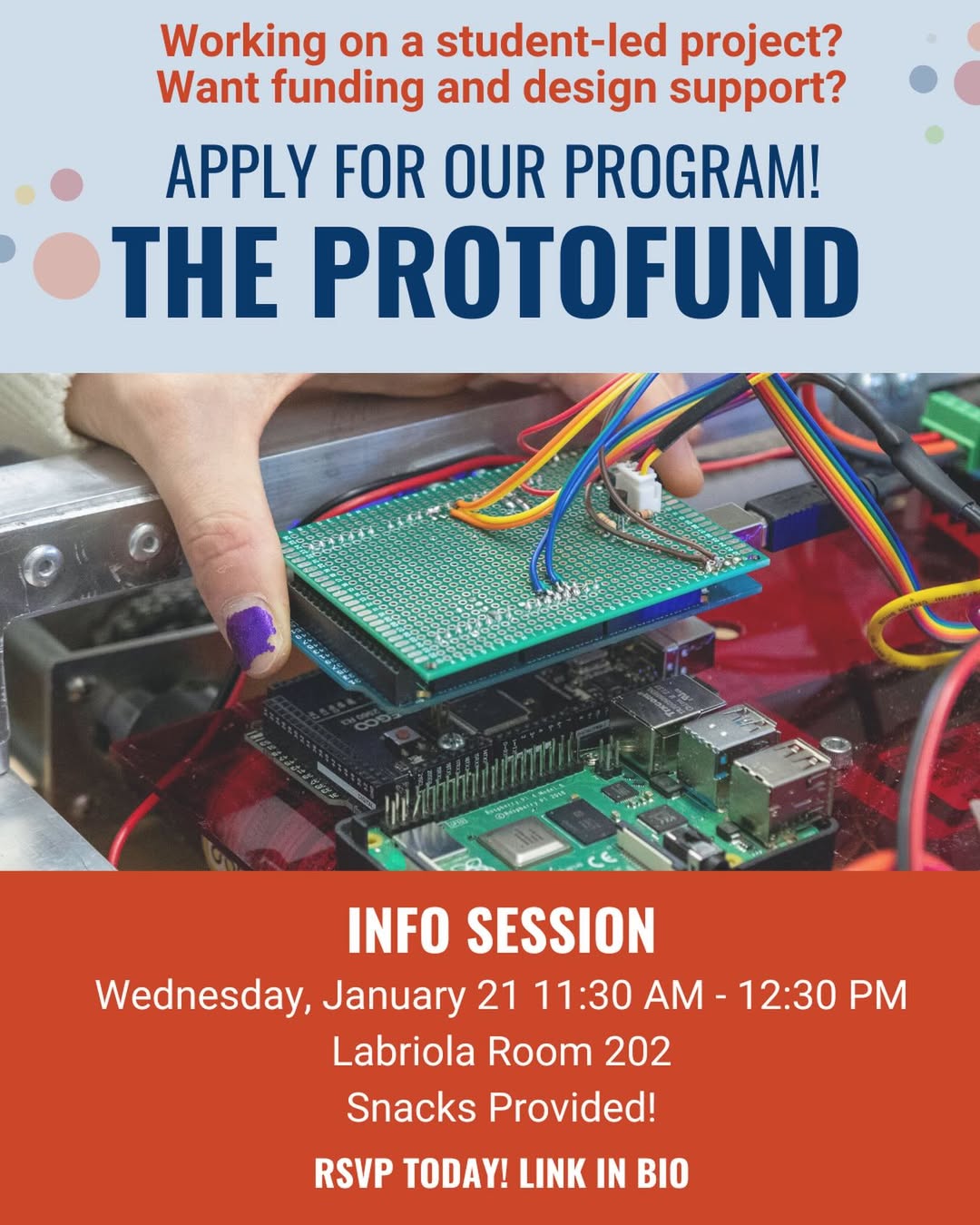
Around this time, I was made aware of the Labriola Protofund program at my college. In their own words, the Labriola Protofund is “a collaborative program offered by the Labriola Innovation Hub with support from faculty and mentors and with funding from generous donations to the E&I Foundation Fund at Colorado School of Mines. The program awards student-led teams up to 2,000 in the second to be used to build prototypes and connects them with the resources, tools, and mentors they need to bring their ideas to reality.” My team consisted of me, Austin, and my roommate, Diego. I made the decision to name the team “Bearing Witness,” which I thought was a neat double entendre. We were literally witnessing bearings, but also a team composed of all Christians, with the express goal of bearing witness to Christ through our work.
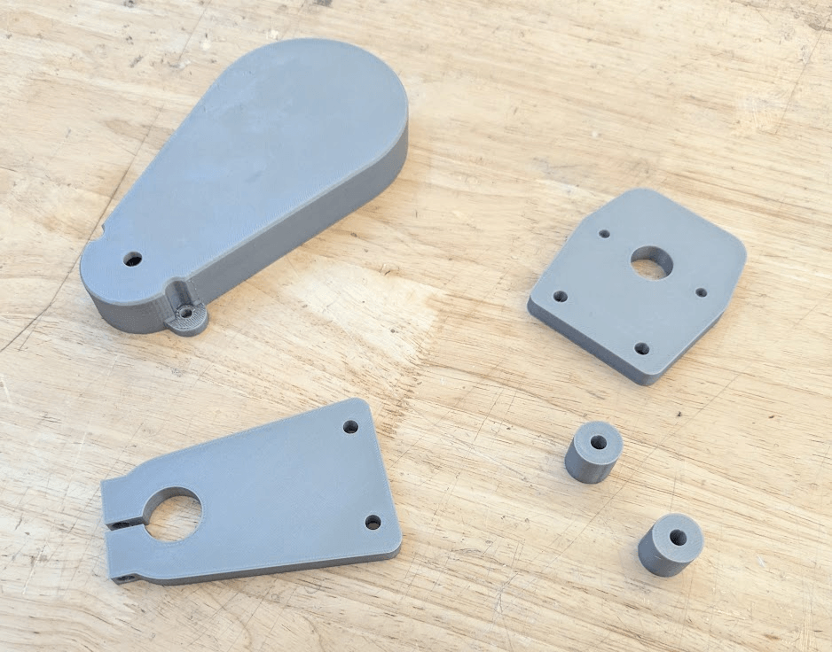
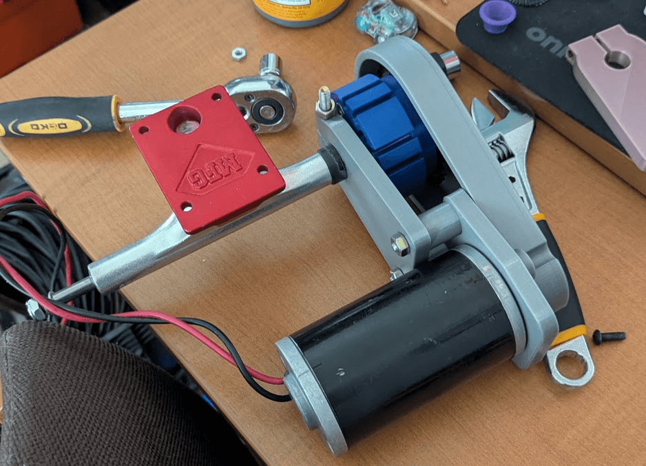
Before getting to the actual urethane casting process, I did a test fit of all the parts. I love that 3D printing makes this type of rapid prototyping possible. By physically assembling the parts, I was able to see how the parts interacted and catch a couple of minor issues before the parts were manufactured. Namely, one of the plates did not have enough tolerance and was pressing on the motor, and the tolerance on the clamp for the truck was far too loose (hence the electrical tape in the picture).
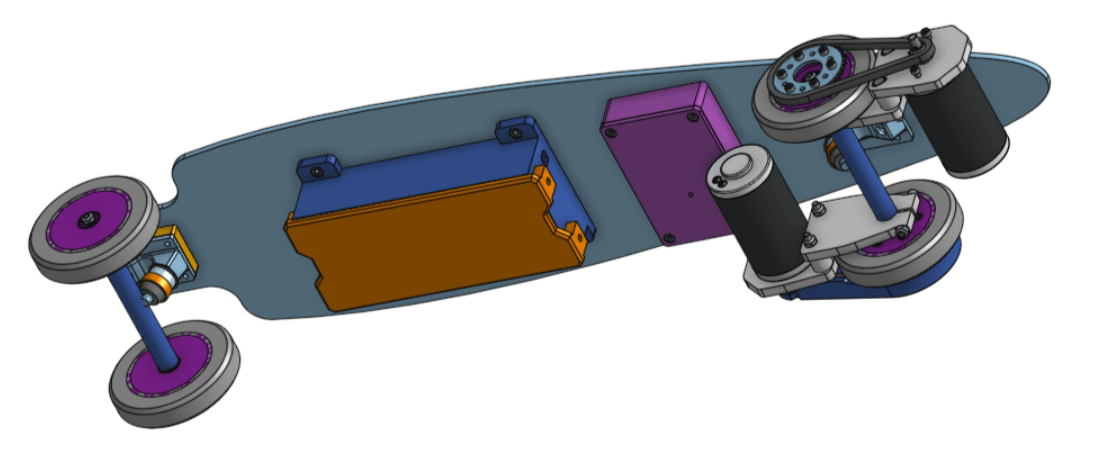
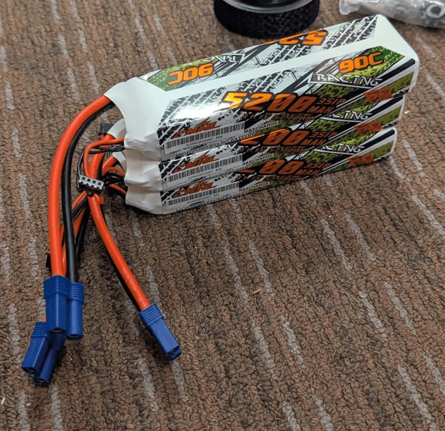
Also during this time, I edited the CAD for the battery housing, opting for 3 3s LiPos from CNHL. With the benefit of hindsight, I wish I would have bought some Molicell 27010 cells and built my own Li-ion battery. Though the CNHL batteries could provide more than enough amps to support the motors, the total capacity left much to be desired. Also, providing a crap-ton of amps to the motors at stall isn't the best idea in most cases anyway. I was budgeting for 200A per motor, which I now realize is pretty ridiculous. If the motors were to pull that for any continuous amount of time, the wires supplying them would just melt their insulation. A max of 60-80A per motor surely would have been fine, and I could have reached that with a 4s3p molicell42A li-ion battery.
Sure enough, after running the numbers, I can say that I could have built a Molicel P42A battery with the same specs for almost $50 less. If I wanted to spend the same amount, I could have had over double the battery capacity.
| link | CNHL Li-Po | Molicel Li-Ion | Molicel Li-Ion |
|---|---|---|---|
| name | CNHL 5.2AH | Molicell P42A | Molicell P42A |
| unit cost | $40.00 | $4.50 | $4.25 |
| nominal voltage | 11.1 | 3.7 | 3.7 |
| capacity (Ah) | 5.2 | 4.2 | 4.2 |
| series # | 1 | 3 | 3 |
| paralell number | 3 | 4 | 8 |
| num cells | 3 | 12 | 24 |
| battery costs | $120.00 | $54.00 | $102.00 |
| extras | EC5 Connectors | Spot Welder & Nickel | Spot Welder & Nickel |
| extra costs ($) | $20.00 | $40.00 | $40.00 |
| total capacity (Wh) | 173.16 | 186.48 | 372.96 |
| total cost | $140.00 | $94.00 | $142.00 |
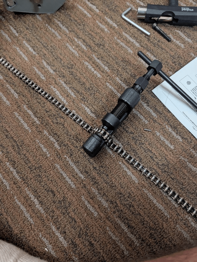
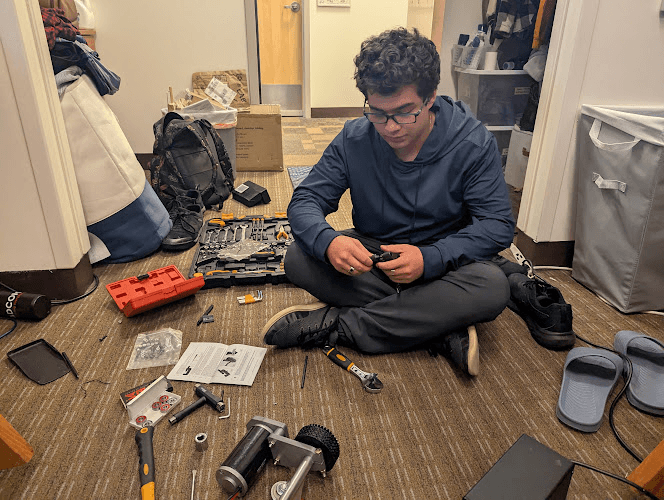
With this done, Diego and I got the chain down to length, and then we were able to bench-test the driving of the hub. In the video above, I quickly wired up an Arduino Uno knockoff to read from an analog joystick and then send an output PWM signal to the connected Spark ESC. The code used for this ended up not being too dissimilar to what I used on actual code for the finished longboard.
Metal Manufacturing
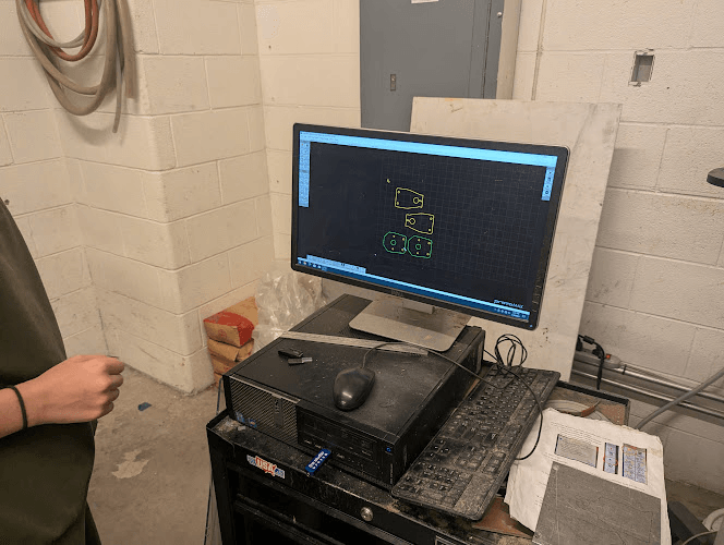
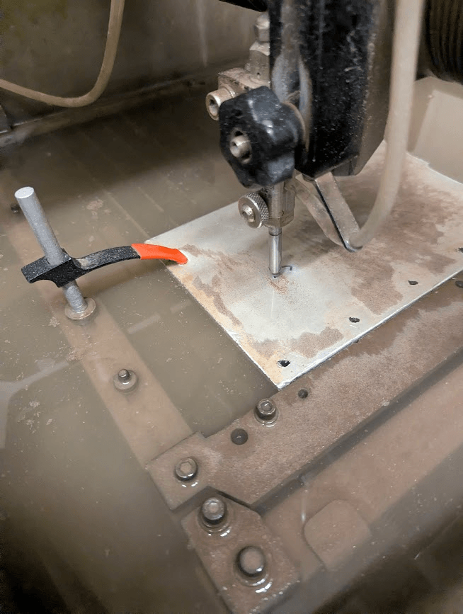
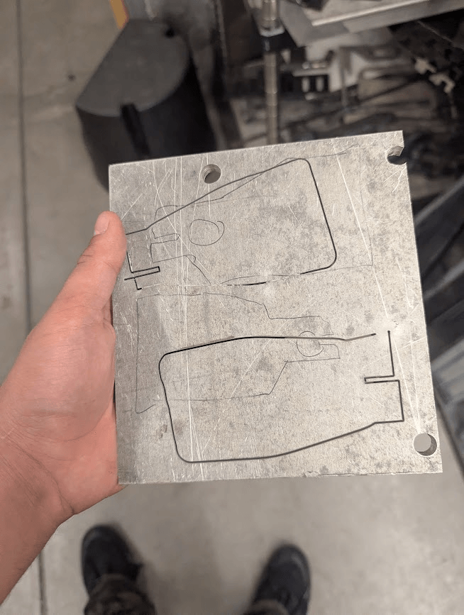
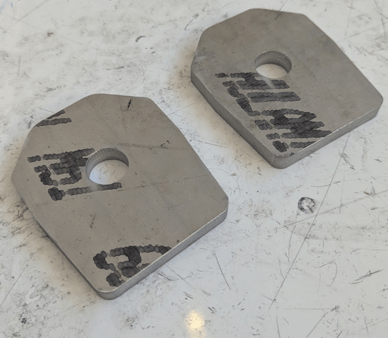
All the sheet plates were cut on the waterjet out of 3/8“ 6061 aluminum plate. The first two parts came out great, but the other two failed. I'm not sure exactly what caused the failure, but I had made the rookie mistake of only having enough material for if nothing went wrong and was learning that lesson the hard way. I was thankfully able to hit up the metals supermarket with a friend who had a car and get some more scrap, but it was still pretty annoying.
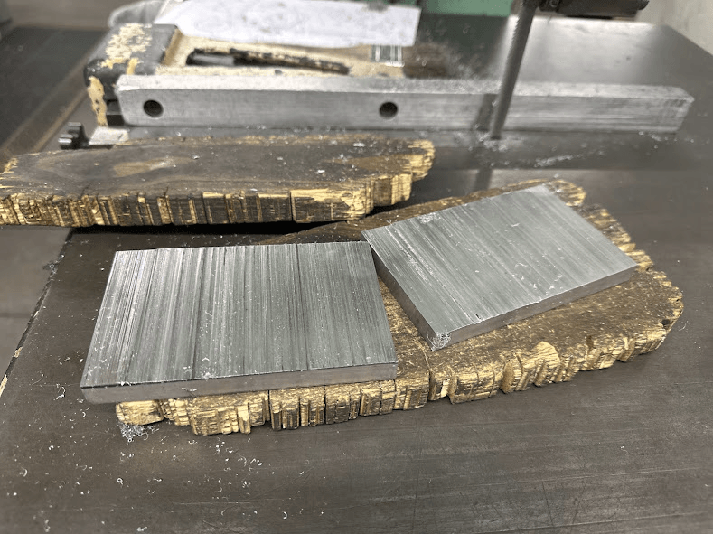
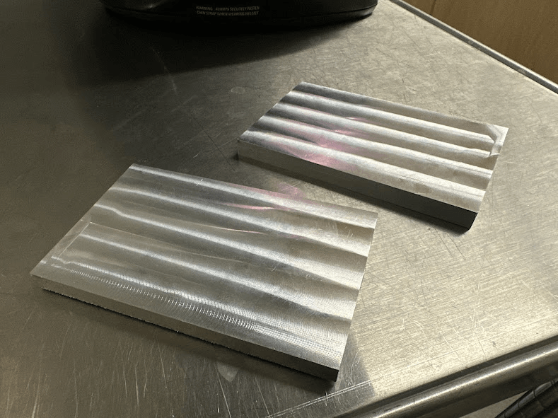
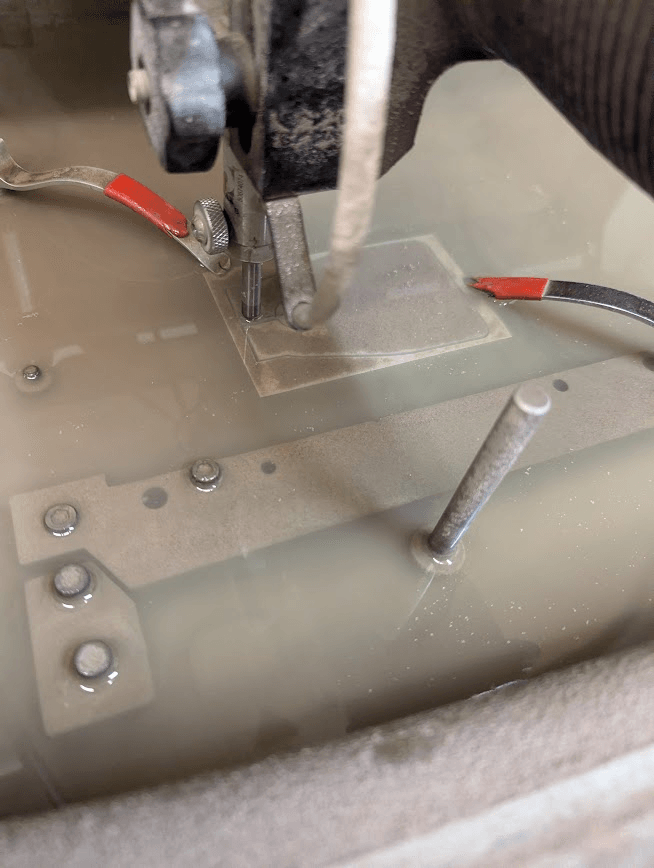
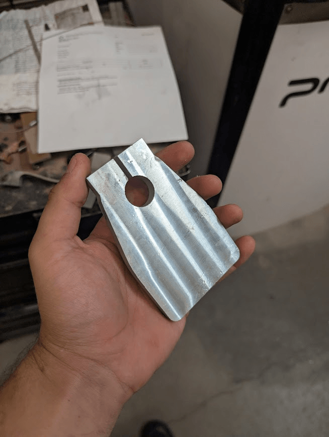
For the remaining parts, my roommate and I had to split our stock, clean it up, and then waterjet it again, making sure it was really clamped down this time.
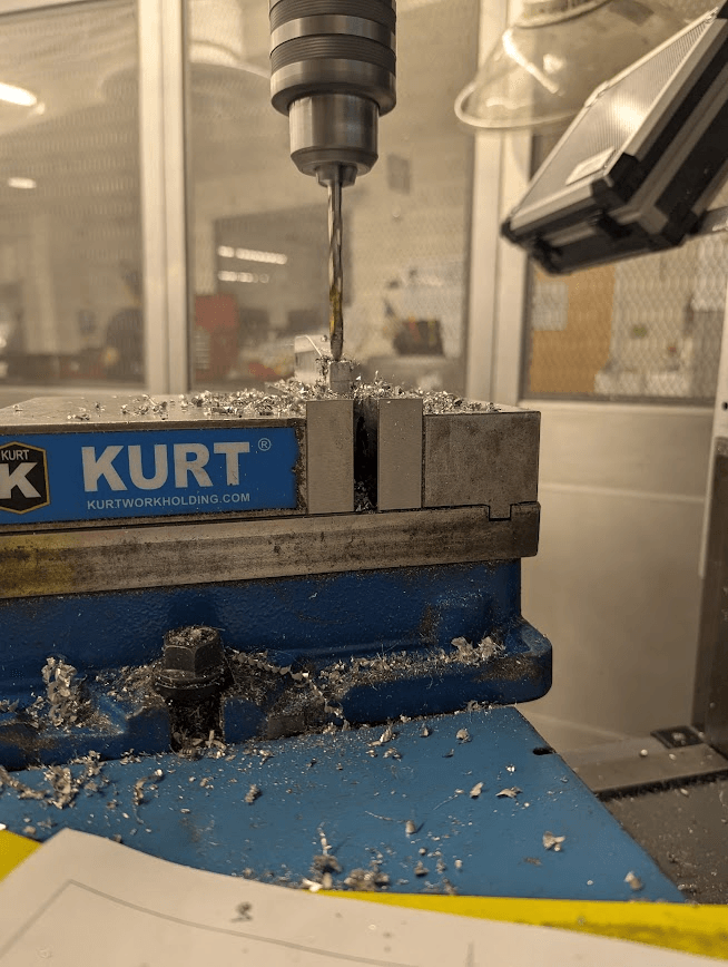
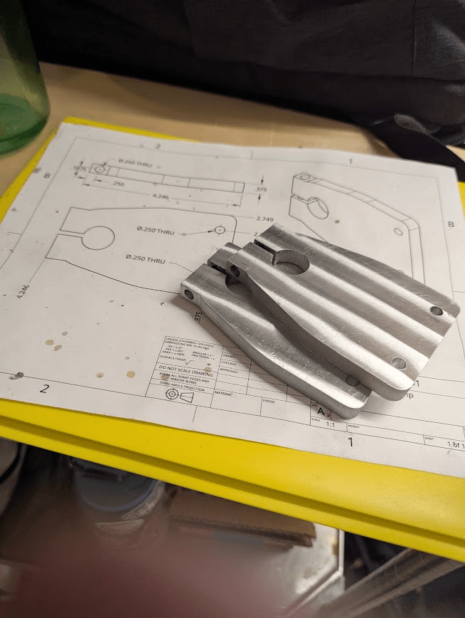
With these done, I just had to drill a couple of holes on the manual mills and turn down some spacers on the lathe. I had actually never used a lathe before, so learning it for this project was a lot of fun. I'd love to use a more powerful lathe where I could crank the feed rate up a bit, but for my small batch of parts, it was okay to take my time. The video has a 2-4x speedup.
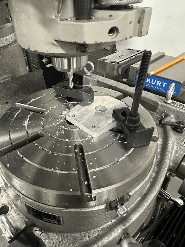
Next, I had Diego machine a little recessed section for the bolts to fit into. He definitely should have just machined them on the CNC mill, but instead he chose to use a rotary table on a manual mill. I hope that learning to use that was worthwhile for him.
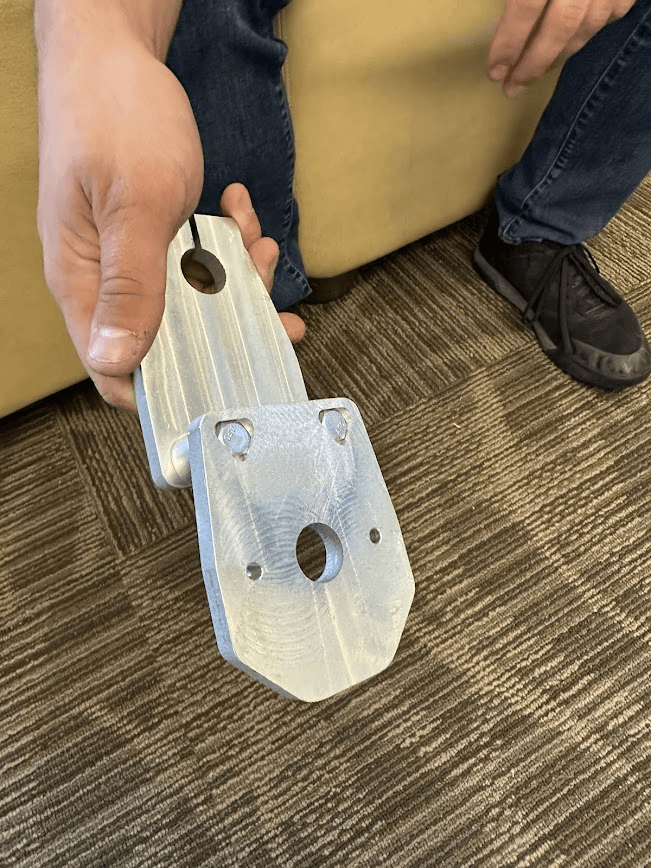
Just like that, our truck clamp assembly was done! It's crazy how it's possible to condense 20+ hours of work into 3 minutes of reading. My teammates and I were pretty hyped, but we knew that we still had a lot to get done, including urethane molding and the entire electronics system.
Battery harness
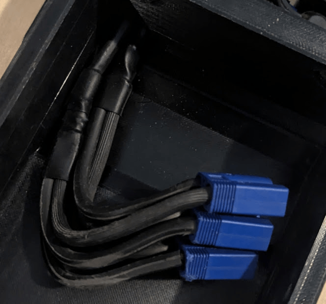
The battery connected through EC5 connectors, and I stupidly chose to use 12AWG wire to carry the current from the batteries to the ESCs. Little did I know that that wire would cause a ton of voltage sag (an estimated 1-2 volts) and melt the surrounding insulation. If this project taught me anything, it's that cutting corners will almost always come back to bite you. There are so many times in this project where I decided to rush something or attempt it without enough research, and these usually resulted in a faster (though jankier) prototype, but they also almost always prompted fixing eventually. Back to EC5s, though, I tried to use my soldering iron to melt solder in the pins, but its 60 watts couldn't handle it, so I had to take it to the electronics lab to solder them with a big-boy 110W iron. EC5 connectors are decent, but they are a massive pain to plug into their housings, so for that reason alone I wish I would have gone with XT90s. I must have spent about one or two whole hours just trying to press those pins in. I used vices, clamps, and screwdrivers to press them in, but I couldn't find any real one-size-fits-all trick for it. Afterward, I would learn that dedicated EC5 press-in tools do actually exist, but at that point it was too late.
Housing and wheels
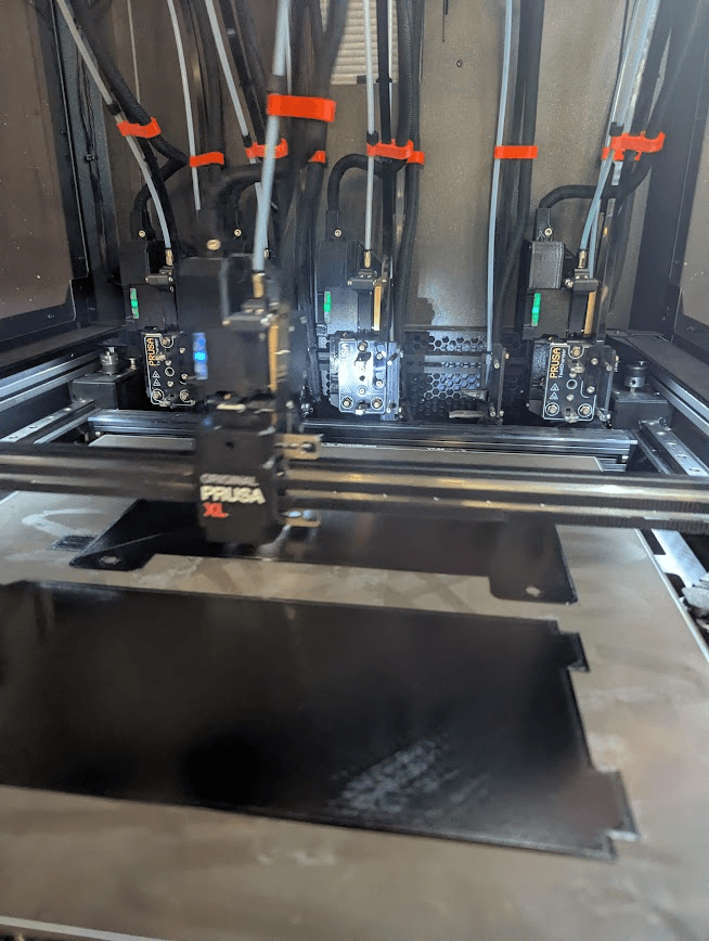
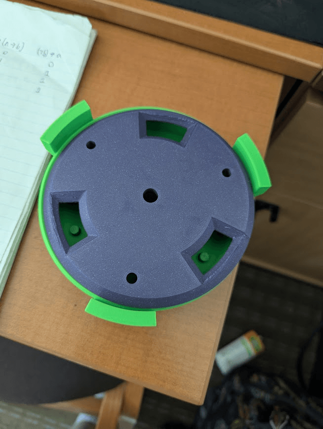
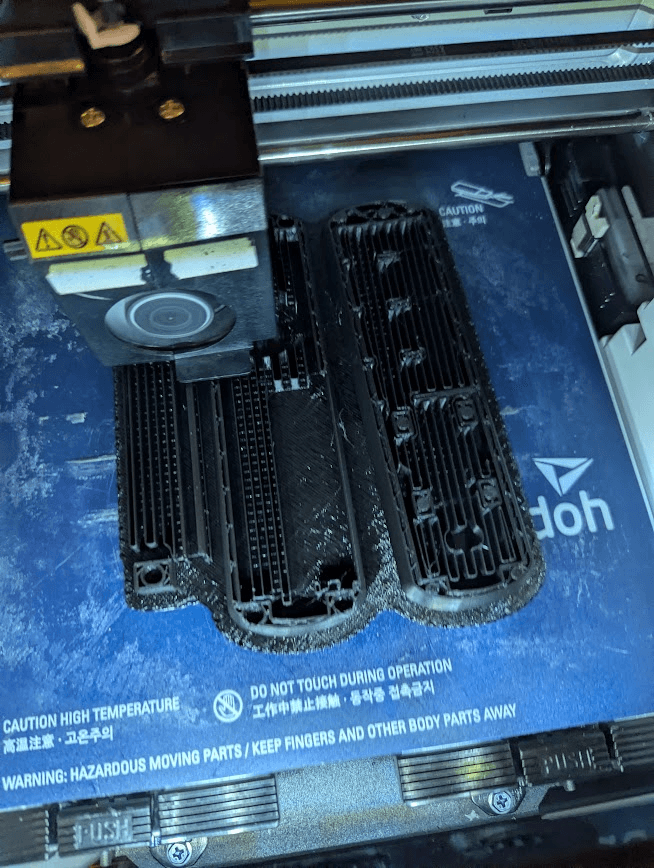
I printed that out of PETG on a Prusa XL printer, which the Mines Maker Society was very gracious to let me use. The first iteration used a hinged design, which would eventually break when I hit a bump. I then re-printed a design that used bolts to secure the lid of the battery box.
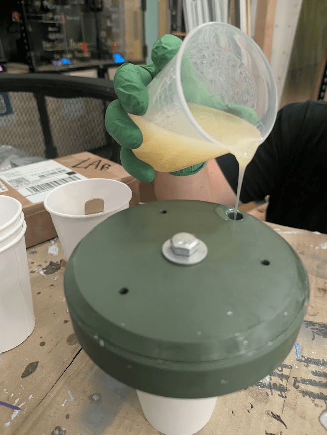
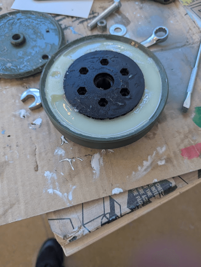
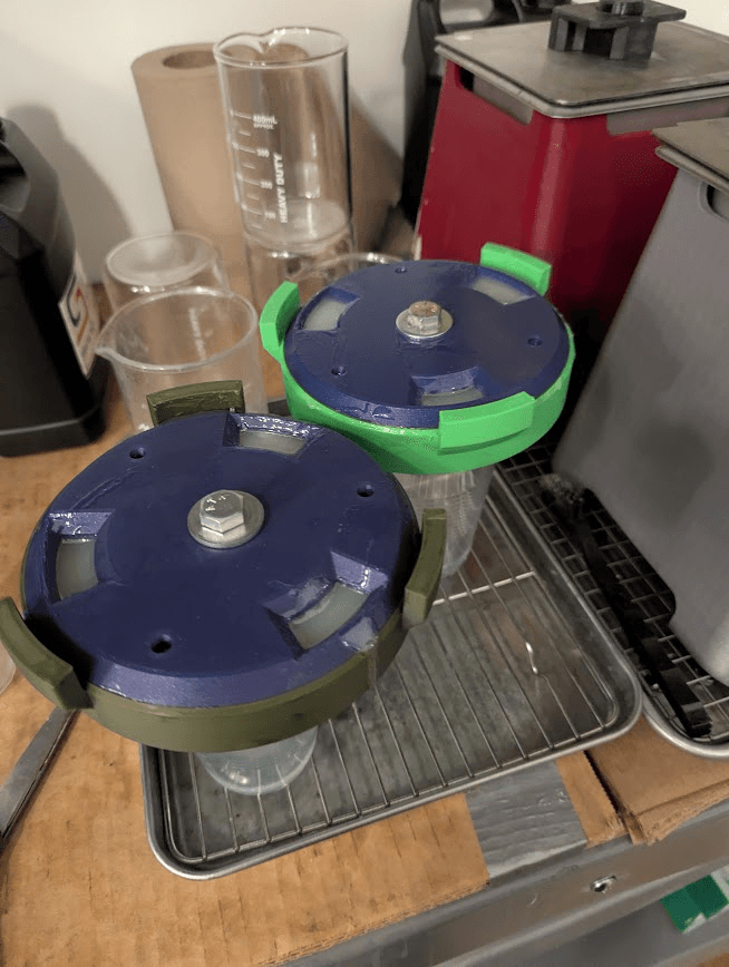
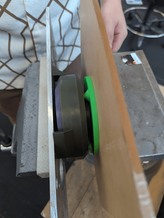
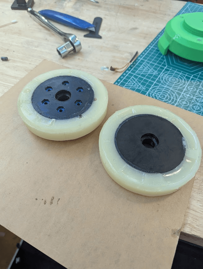
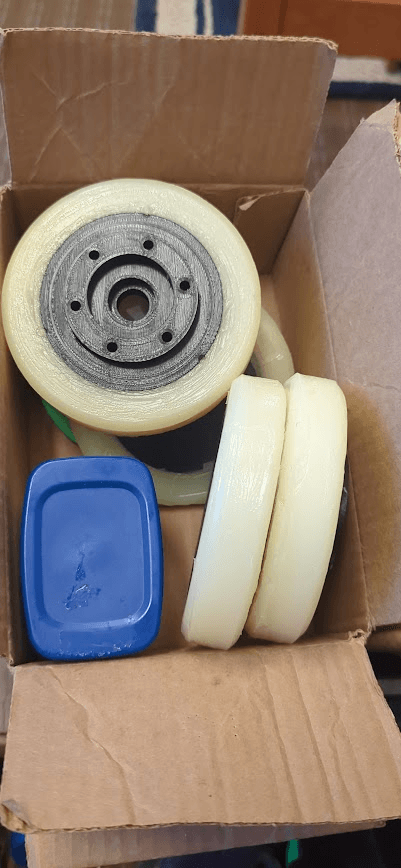
Furthermore, I worked with my floor-mate and friend Ari to cast the wheels out of urethane. The first version only had one hole, but the urethane didn't flow fast enough, so I made a second version utilizing 3 much larger holes. I made the mold with draft angles, thoroughly applied petroleum jelly as a mold release, and even added holes in the back of the mold to push the wheel out with. Regardless, the wheels still managed to get stuck in the mold and required extensive convincing to come out. Perhaps there's some secret knowledge on how to properly do this. Perhaps I just needed to drop some money on some actual mold release.
With all of these hubs, I washed all the petroleum jelly off of them, cut off the excess urethane, and added some captive nuts (yay). I only had two molds at the time, so I had to make the wheels in two separate batches.
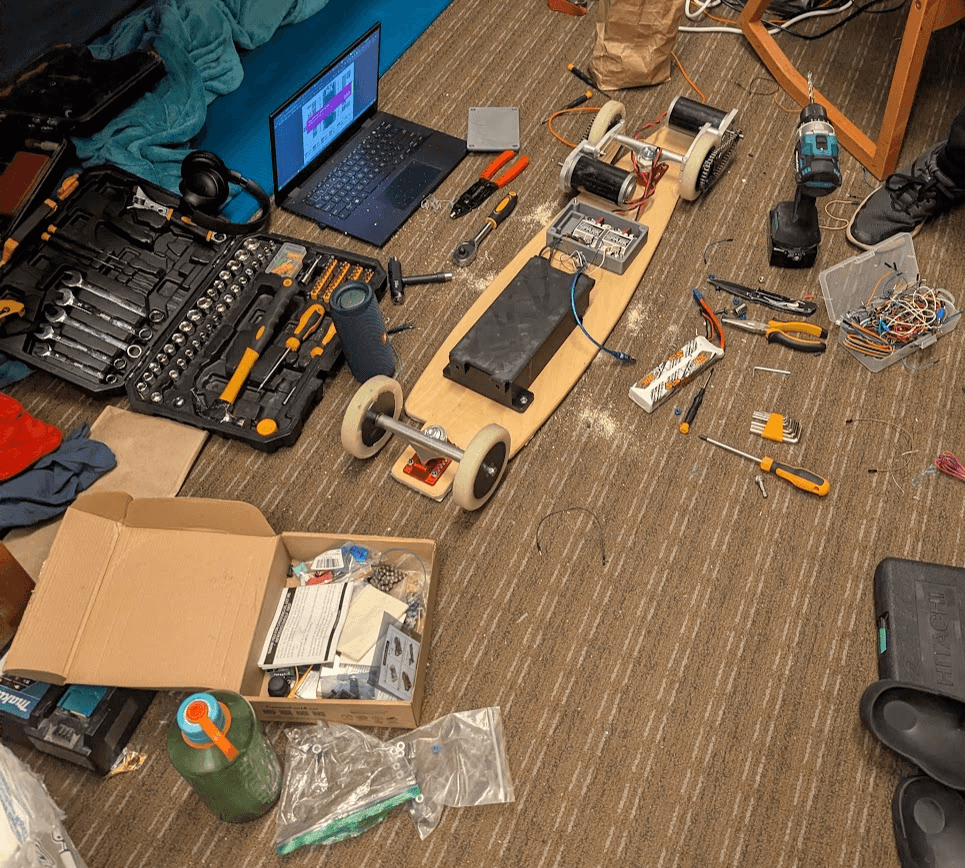
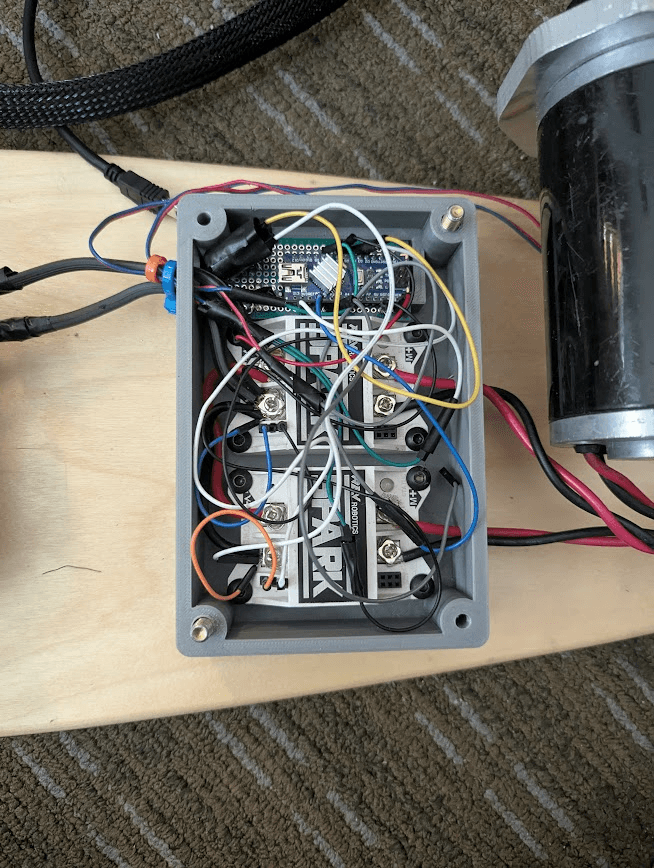
The next day, I added a system to the code to check if the remote was connected every cycle. It would reconfigure the ADC joystick input as an output and then apply a charge to it. Then, after a couple microseconds, it would configure as an input and read if it still had a charge. If it was connected through the joystick, then it would be pulled low through the potentiometer, but if it was disconnected, it would stay high, as it didn't have any ground to discharge to.
At this point, the board was technically done, but as I would learn over the next couple of weeks, it still had many glaring issues.
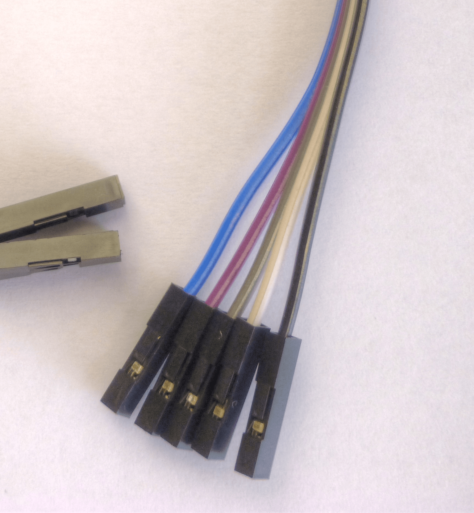
Firstly, I would tear the wires every time I had to stop hard and jump off (which was a lot because I was still relatively new). I re-soldered the wires once, then added a quick-disconnect point with some dupont connectors, but I was aware that this was mega-jank and began thinking about making a remote for the board.
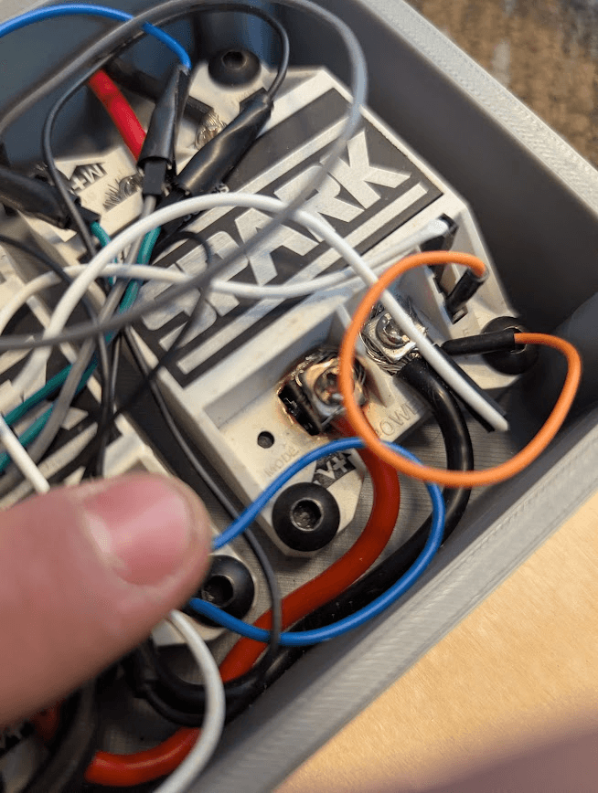
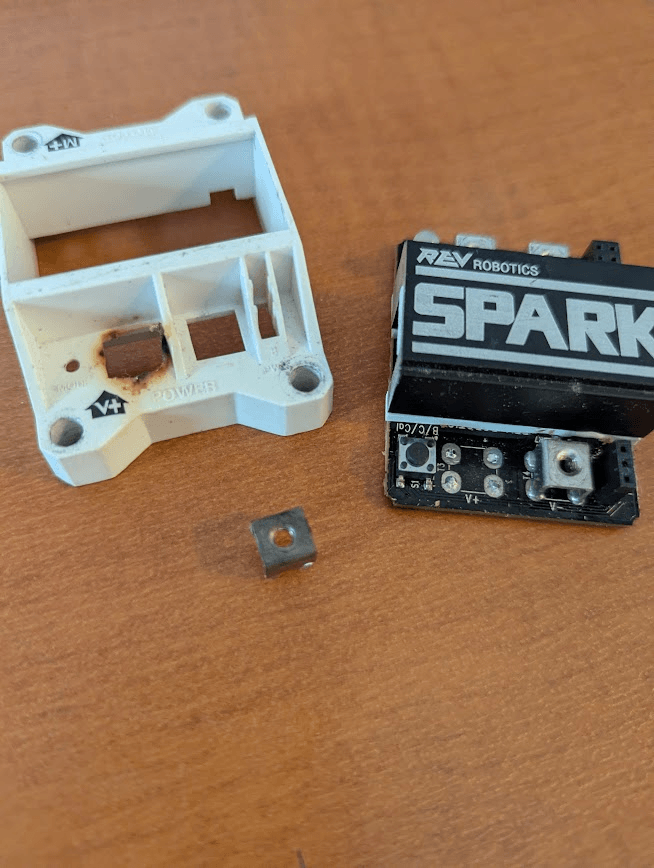
Secondly, one of the contacts for the spark ESCs melted. The connector was not attached tight enough, so I suspect it began arcing, which got the spark hot enough to melt the solder holding the pad on. I posted on Chief Delphi asking for support and got a bit of clarification, which was nice.
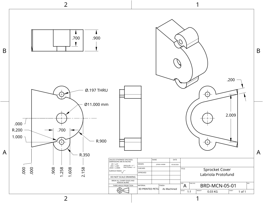
Thirdly, I hit a pothole in the CTLM parking lot at the Colorado School of Mines, and it exploded the housing for the power-transmission assembly. Expecting the same thing to happen again, I made the call to switch to a slimmer version of the assembly covers that would be much more structurally sound if they were to come in contact with asphalt.
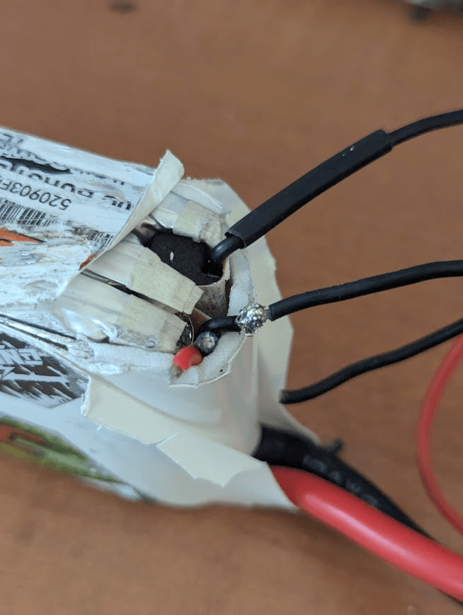
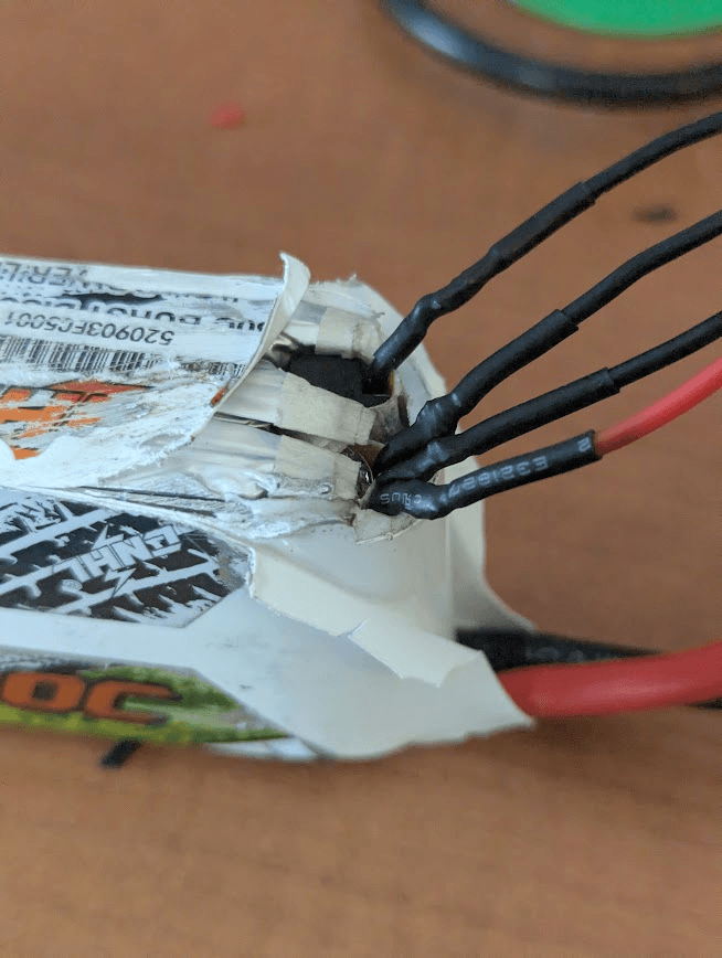
Fourthly, though this is less a fault of the design and more of myself, I forgot to fully tighten the bolts that hold the batteries in. The batteries fell out, resulting in the charging wires for two of them being torn off entirely. I didn't take a picture of them after the incident (reasonable), but I do have some pictures of soldering those back together. It was pretty scary working with leads that were ready to dump 500 amps into each other at a moment's notice, but God's providence ordained that I would be successful. I wrapped all the lipos with a bunch of electrical tape, so it should take longer for the wires to get ground off if the lid ever falls off in the future.
Protofund showcase
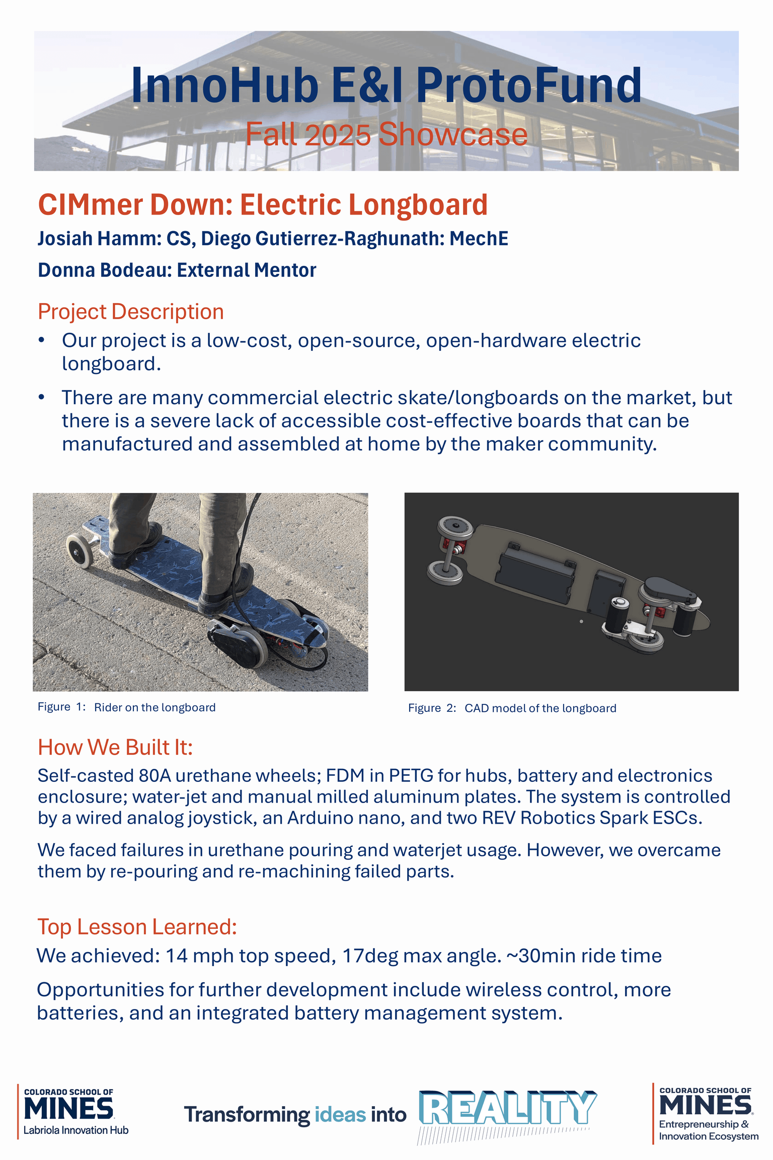
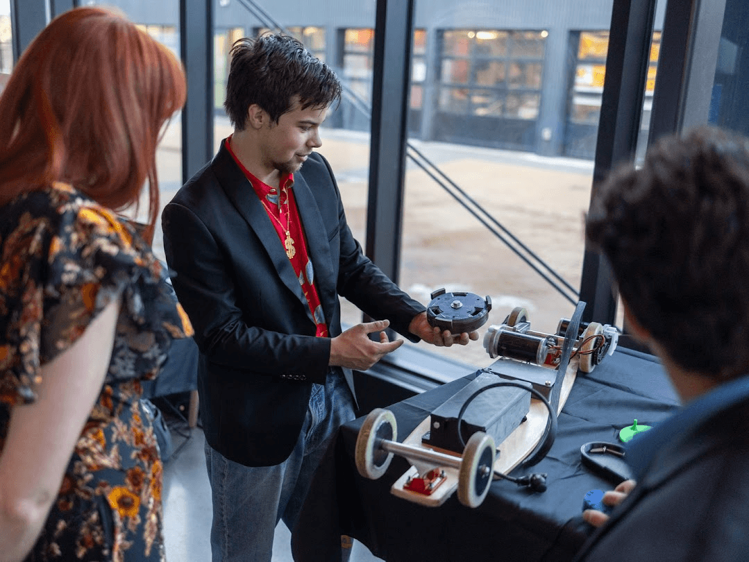
After fixing all these mishaps, however, Diego and I attended the Protofund project showcase. We had a blast demo-ing the project and sharing our progress on it with faculty, including the department head for computer science and the provost for the school. In a funny turn of events, I tore my pants minutes before the presentation, so I had to borrow some shop pants from the metal shop, which were far too big for me. Although pretty embarrassing, it served as a wake-up call about the weight I had gained in the first semester and gave me some urgency to start making healthier choices with food and physical activity.
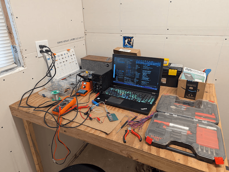
With the fall semester wrapping up, I went home for winter break. Unlike my peers, however, I brought home most of my tools and component boxes, as I would be spending that time making an RF-based remote. Specifically, I went with an NRF24l01 module. When choosing what communication protocol and hardware to use, I was optimizing very heavily for low energy consumption, which is why I landed with the NRF and the Arduino Pro Mini, an ATmega328P-based MCU from the AVR family. One neat thing about this pair is that both of them run on 3.3V, so the voltage only has to be stepped down to 3.3V once, not once to 5V and once to 3.3V, like on the Arduino Nano or similar boards.
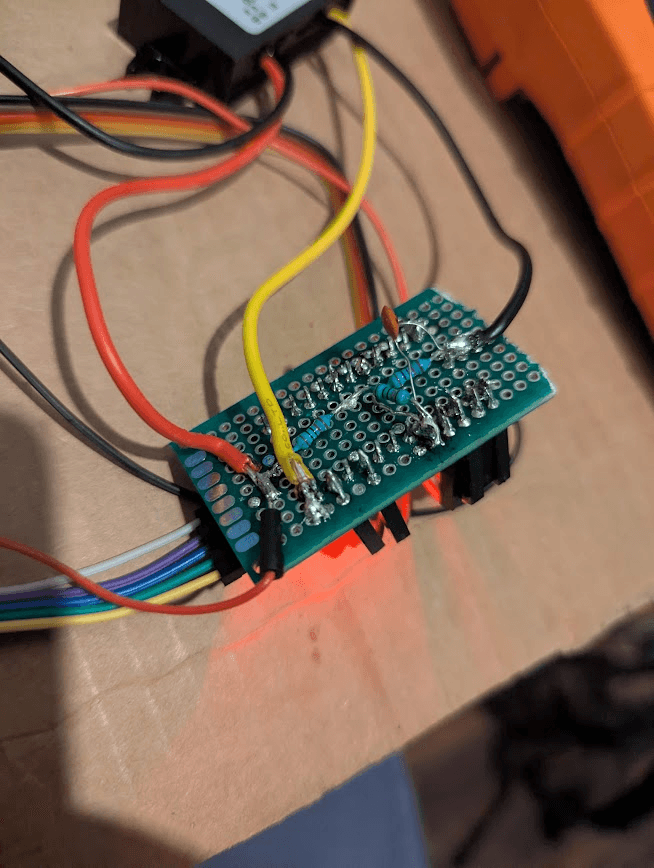
However, the NRF24l01 board is a notoriously fickle piece of technology. I spent over two weeks trying to get them to work how I expected, but in the process, it seemed like I was killing them left and right. With a couple of them, I attempted to desolder the pin header, and destroyed the board in the process. With more, I accidentally shorted the board, instantly frying it. Beyond that, the board seemed to only work when it had a 10 microfarad capacitor across it's power leads, and was being powered by a source that could supply more current than the USB-Serial adapter that I was using to program the remote. I wish I could have known this at the start, because I spent those two weeks in a constant ping-pong between utter despair, confusion, and euphoria.
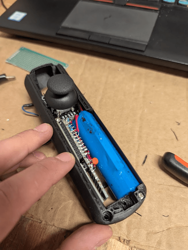
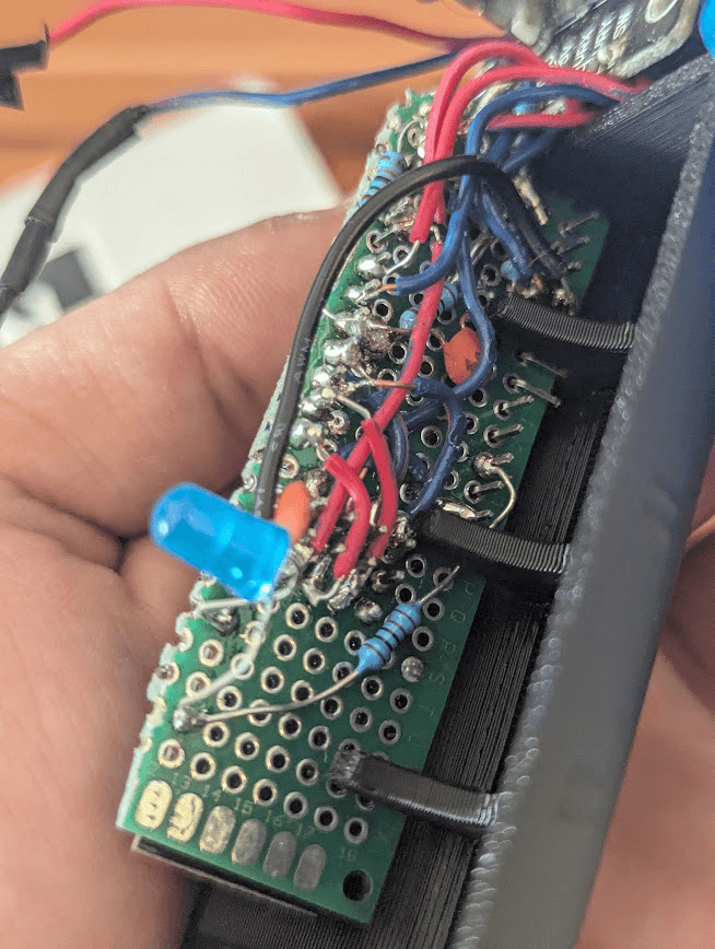
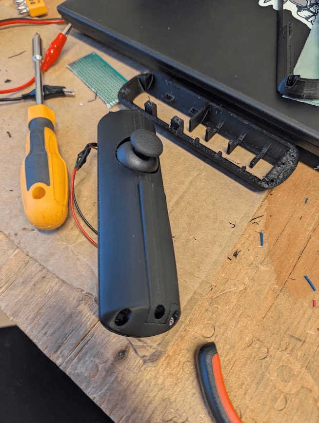
Even so, developing my own remote from scratch gave me an opportunity to get really hands-on with RF electronics, and learn a lot more about electronics in general. I made a voltage divider for measuring the battery voltage with the arduino ADCs, and by doing so built better intuition of resistance, and voltage drop. By messing with capacitors for smoothing out current to the NRF, I learned about the differences between ceramic and electrolytic capacitors, and their different use cases.
Second semester
Without a Protofund Showcase coming up, I was much less motivated to work on CIMmer down during the second semester. It broke about 3 different times, and after each, I would let it sit for a while, lacking the motivation to get it done.
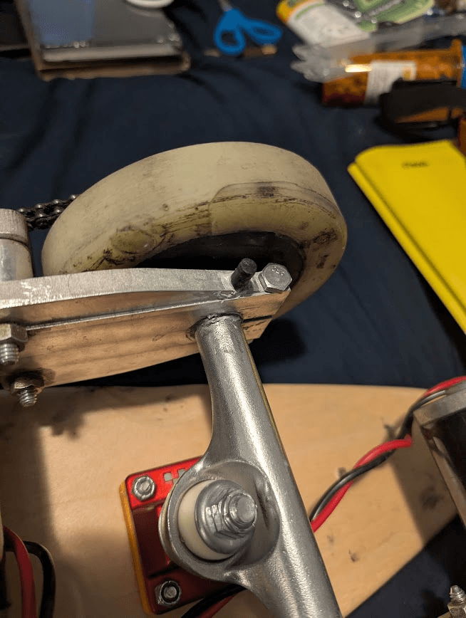
One of the first issues I faced was that the clamps for the trucks were sliding, and no amount of CA glue or JB-weld would hold them on. To solve this, I drilled a hole through both the truck clamp and the truck, and then put a carbon fiber rod into it to hold it in place. This was great, but it also resulted in the board not having enough tilt to make a U-turn without a 50-foot radius. To solve this, I 3d-printed some risers, which solved that problem, but also decreased the stability of the board significantly.
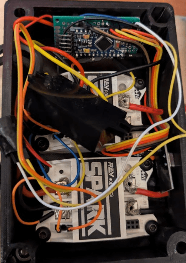
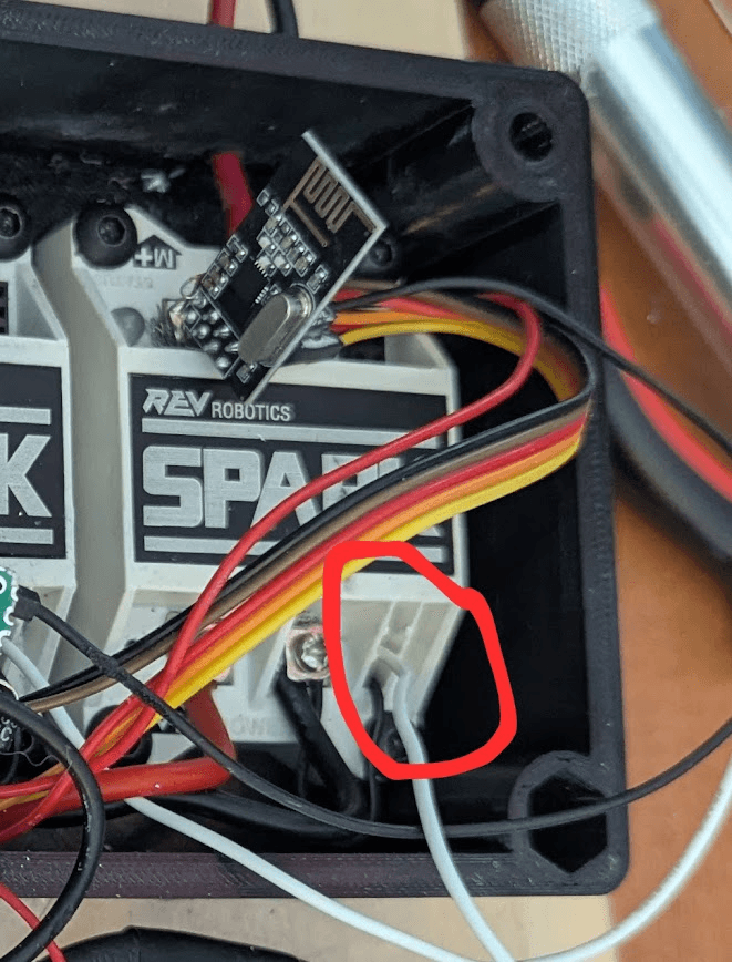
Another issue occurred when I hit a massive bump in the sidewalk, and dislodged the PWM DuPont connectors in the Spark ESC. That would have been bad enough, as it prevented me from riding the board, but providence would have it such that the PWM wire would vibrate and contact the ground-pin, shorting the MCU, and killing the board. To fix this, I soldered the wires directly to the board of the Spark, and re-soldered an entirely new control board for the control box, which took about three hours.
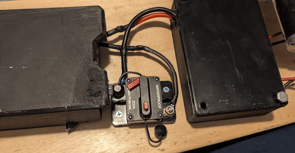
Finally, I replaced the smaller gauge wire with thicker stuff, and added a switch and breaker. Up until this point, I had been manually disconnecting and reconnecting some EC5 connectors to turn the board on and off, so adding this was a great comfort feature. I didn't notice any immediate performance gains from increasing the gauge of the wire, but they don't seem to start melting anymore, so that's pretty cool.
The future of CIMmer down
As of when this was written, the board is killing ESCs, and my best guess is that one of the CIMs has an internal short. Using Sparks and CIMs for the board was a fun novelty, but brushed systems are just so much worse than brushless systems, there isn't really much comparison. The motors cannot run at over 12 volts, they have limited speed and torque, and they get hot fast. Additionally, they don't have any sensing capability built in, so adding a ramp-rate to the control system of the board is pretty much useless.
There were at points the idea of turning this board into an actual project for FRC teams to put their CIMs to use as part of an off-season project, but it is clear to me that the project needs some serious work before reaching that level. I need to:
- Edit the truck clamps to not slip
- Make a PCB for the remote, and test it
- Make a PCB for the board control/receiver
- Design, build, and test a better battery
- Test longevity of CIMs
- Improve control box ventilation
Perhaps when these get done, I could do some interest surveys, and see if there's actually a market for this. Until then, I'm just grateful for the opportunity to have a project to work on. I'm a project-based learner primarily, so having projects like this helps me grasp concepts much more deeply than through a class, and it also gives my brain a sense of purpose and direction, which is good for keeping me on task, and not spiraling into laziness. Either way, the BOM and CAD are on github. A full build guide is not fleshed out, and it likely won't be until all the design revisions are finalized, but you're welcome to reach out to me if you want to know how to build this in the meantime.
“There are no solutions. There are only trade-offs.”
Thanks for reading!